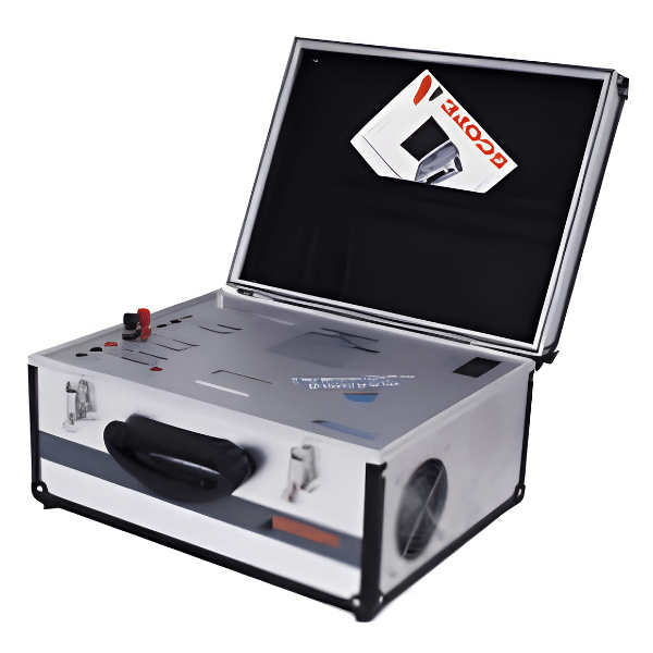
TRM Series

Winding Resistance Meter

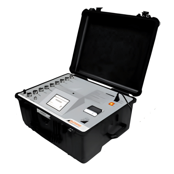
TRM Series Winding Resistance Meters are designed for field testing as well as for factory testing of large rotating machines & transformers up to 1000MVA, 765kV class under live switchyard conditions. DC Winding Resistance values of highly inductive objects like transformers, generators, motor etc. are directly displayed. A backlit LCD with a user-friendly menu sets up the instrument for the test. These meters are protected against the back-emf offered by large inductive windings.
  • 50V DC open circuit voltage for quick stabilization of current
  • Injects up to 25/50 A current and measures resistance up to 2000Ω
  • Has 3/6* Resistance channels, 3/6* Test Current channels and one Temperature input channel
  • Temperature measurement channel and   automatic  temperature correction of winding resistance for copper & aluminium windings
  • One-time connection and simultaneous measurement on three phases of primary or / and* secondary windings
  • It is not necessary to compensate lead resistance, as Kelvin’s four wire measurement method is used
  • OLTC operation and automatic measurement of resistance at all tap positions with indication of OLTC discontinuity, if any
  • Automatic and fast back-emf discharge with indication
  • Demagnetization facility available
  • 7” colour TFT display with touch screen and interactive menu offers easy user interface
  • Inbuilt memory and thermal printer Displays, prints and stores test reports in the form of text header and tabulated test results
  • Can be operated in stand-alone mode or by control through external computer
  • Powerful Windows based software, CTrans TRM offers to setup, operate, capture, view and analyse test data. Test Report can also be generated
  • Housed in rugged IP 67 class molded carrying case for enhanced transport – worthiness
  • The instrument is supplied with Test Lead Set suitable for testing EHV transformers & RTD temperature sensor
  • Type Tested as per IEC 60068, IEC 61326, IEC 61010 & IEC 61000, CE marked
  • OLTC dynamic test facility with current v/s time graph. (Optional)


OLTC Dynamic Testing Feature

Tap changer failures account for a significant number of failures on power transformers. OLTC failures are caused by degradation of OLTC contacts. SCOPE offers dynamic OLTC test facility with TRM to identify weaknesses in the OLTC assembly. The test is conducted in computer control mode at higher sampling speed of 10KHz

  • This test records variation in current flowing through the OLTC during tap change, against time
  • Gives % drop in current and transition time
  • The drop in current during OLTC transition indicates change in transition resistance
  • It is also possible to calculate transition time which shows health of mechanism
  • This optional feature extends the capability of the basic instrument making it ideal test equipment for testing of transformers.

TECHNICAL DATA

Full Product Specifications

Parameters TRM 14 TRM 104 TRM 25 / TRM 25+ TRM 50 / 50+
Resistance Channels 2 2 3 / 6 3 / 6
Temperature Channel Not Available 1
Selectable Current

Ranges

1A, 0.1A, 0.01A 10A, 1A, 0.1A, 0.01A 25A, 10A, 5A, 1A,

0.1A, 0.01A

50A, 40A, 25A, 10A,

5A, 1A, 0.1A, 0.01A

Resistance Range Up to 2000Ω Up to 2000Ω Auto ranging
Best Resolution 1μΩ 0.1μΩ
Accuracy Value ± 0.5% ± 2 digits
Open Circuit Voltage 30V DC 50V DC
Protection Back-EMF, Over temperature, Accidental disconnection of leads
Back-emf Discharge Automatic
Demagnetization Not Available Yes
OLTC Discontinuity

Indication

Yes
Temperature

Correction

Not Available Yes (For Aluminium & Copper)
Display 4 line 20 character backlit LCD 5.7”, 320 x 240 pixels TFT touch screen display
Memory Not Available 100 DUT IDs with 5000 results each
Inbuilt Printer Not Available Thermal printer
Communication Port Not Available Ethernet
Dimensions (mm) 475 x 405 x 175 475 x 405 x 230 630 x 500 x 305 630 x 500 x 305
Instrument Weight 10 kg 15 kg 26 kg 28 kg
OLTC Dynamic Test

Facility (Optional)

Not Available 1 or 3 channels

Related Products

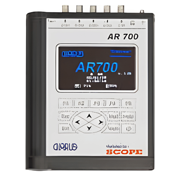
AR700

The AR700 measures acoustic signals with multiple relocatable acoustic sensors mounted on the transformer. The software determines the defect location

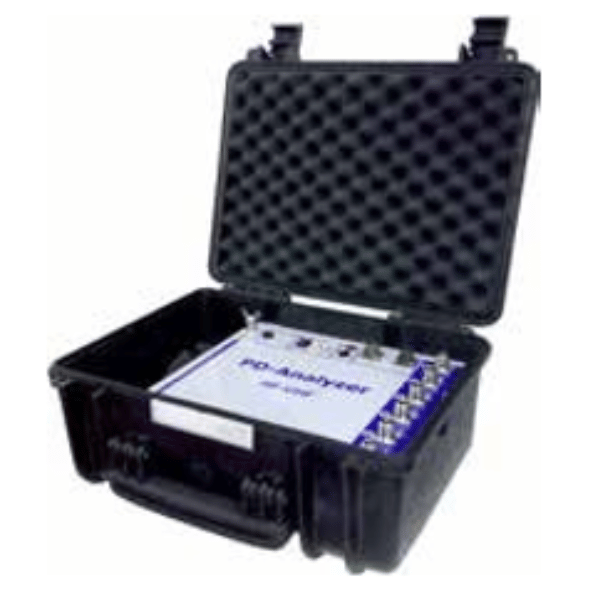
PD Analyser

This is an ‘All in One’ solution for detection, analysis & localisation of partial discharges in the insulation of high-voltage

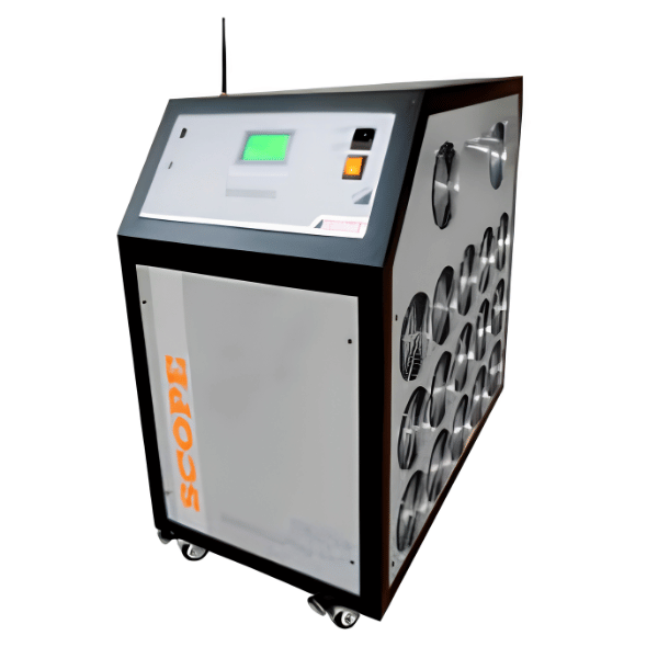
BLUe Series

Battery banks have become an inseparable part of uninterrupted or back-up power supply arrangements in various industries like Power, Telecom,